| Light and Transparencies |
When light traverses a transparent film, some energy is absorbed and the rest is transmitted to other side of the film. The percentage of light that is transmitted may be defined as Transparency Coefficient.
When several films are in the same direction of light, the correspondent transparency coefficients are multiplied. The goal of this problem is to determine the percentage of light that is projected on the ground, after traversing a given set of films.

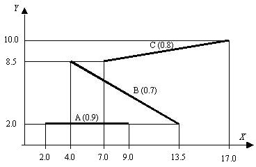
Consider the set of lines segments in fig. 1. They represent
transparent films in the above conditions (transparency
coefficients are written in brackets). Also consider that light is
propagating in the vertical direction, from top to bottom.
Accordingly to the figure, the end points of the lines define a set of projected segments onto the ground (ground is represented by the X axe). For each projected segment, it is possible to evaluate the percentage of light that reaches the ground and, for the entire set of segments, a list can be obtained:
-inf, 2.0 -> 1.000
2.0, 4.0 -> 0.900
4.0, 7.0 -> 0.630
7.0, 9.0 -> 0.504
9.0, 13.5 -> 0.560
13.0, 17.0 -> 0.800
17.0, +inf -> 1.000
To simplify the problem, it is assumed that neither vertical lines
nor crossing lines are given. Also no coincidences exist in the
vertical projection of all given points (in other words, the
X coordinates of the end points are all different
from each other). On the other hand, a coordinate may be any real
value from - ![]() to +
to + ![]() .
.
The input is a text file containing several lines, as follows.
The first line of the input contains the number NL (integer format) of line segments. It is followed by NL lines of text defining, each one, a line segment.
Accordingly to the above explanations, a line segment is defined by the coordinates of its two end points P1 and P2 and the transparency coefficient r, in the sequence x1 y1 x2 y2 r, separated by single spaces (all the five values are in the real format). No order is considered for the two points P1 and P2.
The first line of the output contains the number NP (integer format) of projected segments. It is followed by NP lines of text, defining, each one, a projected segment. These lines must be sorted in ascending order of X values.
A projected segment must be defined by its coordinates X1 and X2, followed by the evaluated percentage of light. All the tree values must be in real format, rounded to 3 decimal digits and separated by single spaces. Infinite values must be represented by `-inf' or `+inf'.
1

3
2.0 2.0 9.0 2.0 0.9
13.5 2.0 4.0 8.5 0.7
17.0 10.0 7.0 8.5 0.8
7
-inf 2.000 1.000
2.000 4.000 0.900
4.000 7.000 0.630
7.000 9.000 0.504
9.000 13.500 0.560
13.500 17.000 0.800
17.000 +inf 1.000