An approach of representing the stresses (force per unit area) on a body is the Mohr's Circle - devised by Otto Mohr in 1882. It's a very nice method of representing the stresses and analyze where they occur, so it's used widely. In this problem we are not concerned with the details of the theory, we will just know how to use this device at work.
Let a stress state is
described by two principle stresses (Load which tries to compress or elongate)
![]() ,
,
![]() and two torsional
stresses (Load which tries to twist)
and two torsional
stresses (Load which tries to twist)
![]() ,
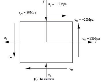
,![]() as shown in the example below, Figure a. As
as shown in the example below, Figure a. As
![]() is
always equal to
is
always equal to![]() but in reverse direction, in the input these will be given as
but in reverse direction, in the input these will be given as
![]() ,
,
![]() and
and![]() .
Thus input for the following condition is (32, -10, 20, CCW).
.
Thus input for the following condition is (32, -10, 20, CCW).
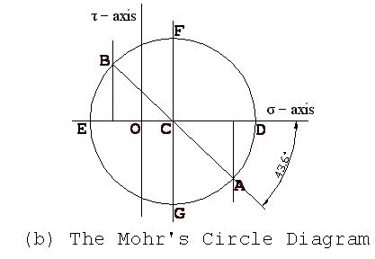
Step 1 : Draw two perpendicular line indicating
horizontal line as
![]() axis and the vertical line as
axis and the vertical line as
![]() axis. The point of
intersection is the center point (0,0) and both the stresses is zero there. See Figure
b below.
axis. The point of
intersection is the center point (0,0) and both the stresses is zero there. See Figure
b below.
Step 2 : Locate points (![]() ,
,![]() )
and (
)
and (![]() ,
,![]() )
and connect them with a straight line. Indicated by point A (32,
-20) and
B (-10, 20) respectively in Figure b.
)
and connect them with a straight line. Indicated by point A (32,
-20) and
B (-10, 20) respectively in Figure b.
Step 3 : Draw a circle with the line
AB as the
diameter and the intersection of the line AB and
DE (![]() axis) as the center
(point C).
axis) as the center
(point C).
Now for maximum normal stress condition:
>> Maximum normal stress angle = half of angle ACD = 43.6 / 2 = 21.8 degree. Angle ACD will not be greater than 90 degree only for current problem.
>> Maximum and minimum normal stress = OD and OE respectively = 40 & -18 respectively.
For maximum shear stress condition
>> Maximum shear stress angle = half of angle ACD + 45 = 21.8 + 45 = 66.8 degree
>> Maximum shear stress = CF = 29
>> Normal stress at this condition = OC = 11
Remember, on the ordinate
clockwise (CW) shear stresses are plotted up; counterclockwise (CCW) shear
stresses are plotted down. Moreover
![]() always has the same
value as
always has the same
value as
![]() but
inverse in direction,
but
inverse in direction,
i.e.
![]() =
-
=
-![]() .
.
After that print maximum shear stress angle as stated in the example above (angle ACD + 45). On the next line print the value of CF, followed by the value of CO.
Each real number must be rounded to the nearest 2 digits after the decimal point. Consider the format of the sample output below while printing the values. Output a blank line between two consecutive output set.
32 -10 20 CCW
80 -40 0
Element : 1
Position of maximum normal stresses : 21.80 deg
Maximum normal stresses : 40.00 MPa and -18.00 MPa

Position of maximum shear stresses : 66.80 deg
Maximum shear stress (xy plane) : 29.00 MPa
Normal stress at this condition : 11.00 MPa

Element : 2
Position of maximum normal stresses : 0.00 deg
Maximum normal stresses : 80.00 MPa and -40.00 MPa

Position of maximum shear stresses : 45.00 deg
Maximum shear stress (xy plane) : 60.00 MPa
Normal stress at this condition : 20.00 MPa